Monday, August 16, 2021

Routh- Hurwitz Criterion | Stable System | marginally stable | Unstable system | control system

Routh- Hurwitz Criterion:

Stable System: 

  If all the roots of the characteristic equation lie on the left half of the 'S' plane then the system is said to be a stable system.

Marginally Stable System: 

  If all the roots of the system lie on the imaginary axis of the 'S' plane then the system is said to be marginally stable.

Unstable System: 

  If all the roots of the system lie on the right half of the 'S' plane then the system is said to be an unstable system.


Statement of Routh-Hurwitz Criterion:

  Routh Hurwitz criterion states that any system can be stable if and only if all the roots of the first column have the same sign and if it does not has the same sign or there is a sign change then the number of sign changes in the first column is equal to the number of roots of the characteristic equation in the right half of the s-plane i.e. equals to the number of roots with positive real parts.


Necessary but not sufficient conditions for Stability:

  We have to follow some conditions to make any system stable, or we can say that there are some necessary conditions to make the system stable.


Consider a system with characteristic equation:


1. All the coefficients of the equation should have the same sign.

2. There should be no missing term.


If all the coefficients have the same sign and there are no missing terms, we have no guarantee that the system will be stable. For this, we use Routh Hurwitz Criterion to check the stability of the system. If the above-given conditions are not satisfied, then the system is said to be unstable. This criterion is given by A. Hurwitz and E.J. Routh.


Advantages of Routh- Hurwitz Criterion:

1. We can find the stability of the system without solving the equation.

2. We can easily determine the relative stability of the system.

3. By this method, we can determine the range of K for stability.

4. By this method, we can also determine the point of intersection for root locus with an imaginary axis.

Limitations of Routh- Hurwitz Criterion:

1. This criterion is applicable only for a linear system.

2. It does not provide the exact location of poles on the right and left half of the S plane.

3. In case of the characteristic equation, it is valid only for real coefficients.

The Routh- Hurwitz Criterion:

Consider the following characteristic Polynomial

When the coefficients a0, a1, ......................an are all of the same sign, and none is zero.


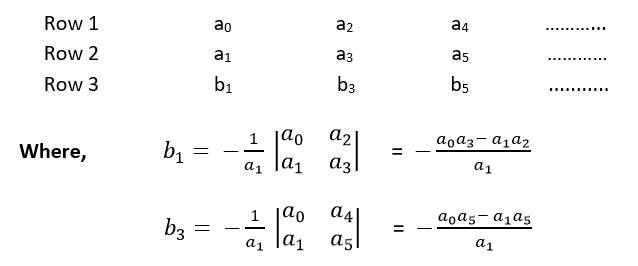
Step 1: Arrange all the coefficients of the above equation in two rows:

Step 2: From these two rows we will form the third row:

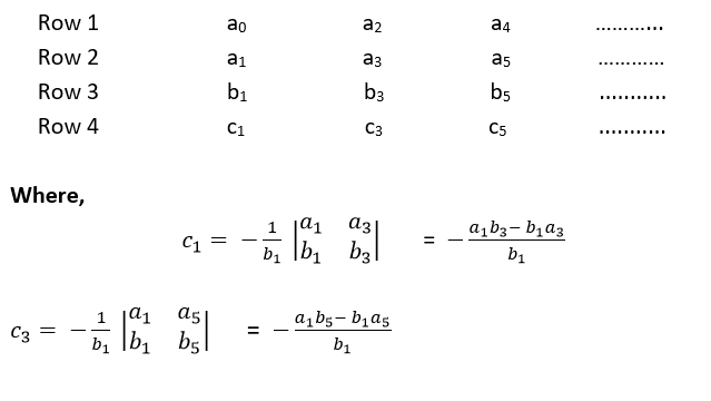
Step 3: Now, we shall form fourth row by using second and third row:

Step 4: We shall continue this procedure of forming a new rows:


Example

Check the stability of the system whose characteristic equation is given by


s⁴ + 2s³+6s²+4s+1 = 0


Solution

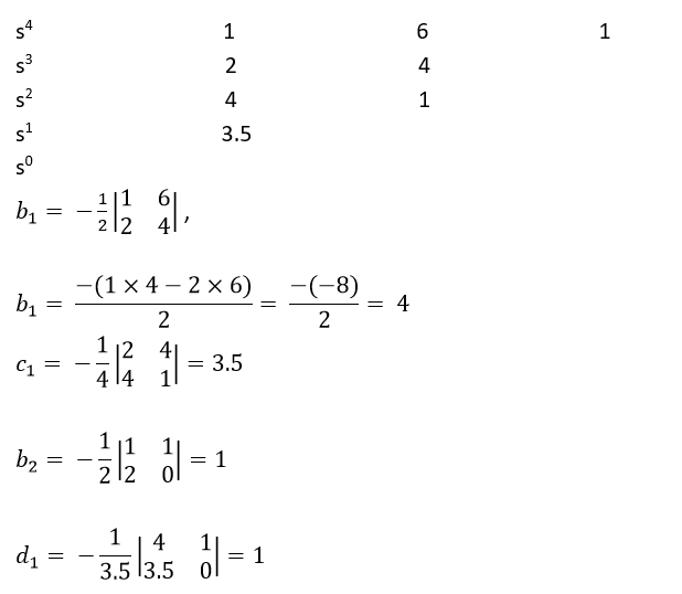
Obtain the arrow of coefficients as follows


Since all the coefficients in the first column are of the same sign, i.e., positive, the given equation has no roots with positive real parts; therefore, the system is said to be stable.

Labels: , , , , ,

Sunday, August 15, 2021

Time domain specifications | Delay Time | Rise Time | Peak Time | Maximum Peak | Settling Time | Steady State error | control system

Time Domain Specifications:

  All the time domain specifications are represented in this figure. The response up to the settling time is known as transient response and the response after the settling time is known as steady state response.


  The performance of the control system are expressed in terms of transient response to a unit step input because it is easy to generate initial condition basically are zero.

Following are the common transient response characteristics:

1. Delay Time.
2. Rise Time.
3. Peak Time.
4. Maximum Peak.
5. Settling Time.
6. Steady State error.


Delay Time:

  The time required for the response to reach 50% of the final value in the first time is called the delay time.

Rise Time:

  The time required for response to rising from 10% to 90% of final value, for an overdamped system and 0 to 100% for an underdamped system is called the rise time of the system.

Peak Time:

The time required for the response to reach the 1st peak of the time response or 1st peak overshoot is called the Peak time.

Maximum overshoot:

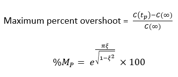
  The difference between the peak of 1st time and steady output is called the maximum overshoot. It is defined by


Settling Time (ts):

  The time that is required for the response to reach and stay within the specified range (2% to 5%) of its final value is called the settling time.

Steady State Error (ess):

  The difference between actual output and desired output as time't' tends to infinity is called the steady state error of the system.

Example - 1:

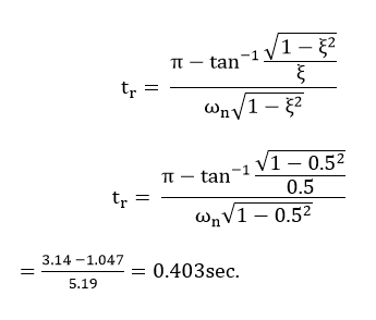
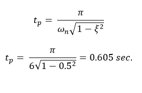
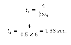
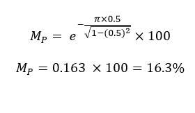
When a second-order system is subjected to a unit step input, the values of ξ = 0.5 and ωn = 6 rad/sec. Determine the rise time, peak time, settling time and peak overshoot.

Solution:

Given-
ξ = 0.5 ω n = 6 rad/sec 
 
Rise Time:

Peak time: 

Settling Time:

Maximum overshoot:


Labels: , , , , , , ,

Time domain analysis of a control system | Step Function | Ramp Function | Parabolic Function | Impulse Function | Time Response of First Order Control Systems(step, ramp, impulse) | Control System

In a control system, there may be some energy storing elements attached to it. Energy storing elements are generally inductors and capacitors in case of an electrical system. Due to the presence of these energy storing elements, if the energy state of the system is disturbed, it will take a certain time to change from one energy state to another. The exact time taken by the system for changing one energy state to another is known as transient time and the value and pattern voltages and currents during this period are known as the transient response.

A transient response is normally associated with an oscillation, which may be sustained or decaying in nature. The exact nature of the system depends upon the parameters of the system. Any system can be represented with a linear differential equation. The solution of this linear differential equation gives the response of the system. The representation of a control system by a linear differential equation of functions of time and its solution is collectively called time domain analysis of the control system.

Step Function:

  Let us take an independent voltage source or a battery which is connected across a voltmeter via a switch, ‘s’. It is clear from the figure below, whenever the switch ‘s’ is open, the voltage appears between the voltmeter terminals is zero. If the voltage between the voltmeter terminals is represented as v (t), the situation can be mathematically represented as

Now let us consider at t = 0, the switch is closed and instantly the battery voltage V volt appears across the voltmeter and that situation can be represented as,

Combining the above two equations we get

In the above equations if we put 1 in place of k, we will get a unit step function which can be defined as

Now let us examine the Laplace transform of unit step function. Laplace transform of any function can be obtained by multiplying this function by e^-st and integrating multiplied from 0 to infinity.

If input is R(s), then

Ramp Function:

  The function which is represented by an inclined straight line intersecting the origin is known as ramp function. That means this function starts from zero and increases or decreases linearly with time. A ramp function can be represented as,

Here in this above equation, k is the slope of the line.

Now let us examine the Laplace transform of ramp function. As we told earlier Laplace transform of any function can be obtained by multiplying this function by e-st and integrating multiplied from 0 to infinity.,


Parabolic Function:

  Here, the value of function is zero when time t<0 and is quadratic when time t > 0. A parabolic function can be defined as,

  Now let us examine the Laplace transform of parabolic function. As we told earlier Laplace tranform of any function can be obtained by multiplying this function by e-st and integrating multiplied from 0 to infinity.

Impulse Function:

  Impulse signal is produced when input is suddenly applied to the system for infinitesimal duration of time. The waveform of such signal is represented as impulse function. If the magnitude of such function is unity, then the function is called unit impulse function. The first time derivative of step function is impulse function. Hence Laplace transform of unit impulse function is nothing but Laplace transform of first-time derivative of unit step function.


Time Response of First Order Control Systems:

  When the maximum power of s in the denominator of a transfer function is one, the transfer function represents a first order control system. Commonly, the first order control system can be represented as


Time Response for Step Function:

  Now a unit step input is given to the system, then let us analyze the expression of the output:


It is seen from the error equation that if the time approaching to infinity, the output signal reaches exponentially to the steady-state value of one unit. As the output is approaching towards input exponentially, the steady-state error is zero when time approaches to infinity.


Let us put t = T in the output equation and then we get,


This T is defined as the time constant of the response and the time constant of a response signal is that time for which the signal reaches to its 63.2 % of its final value. Now if we put t = 4T in the above output response equation, then we get,


When the actual value of the response reaches to the 98% of the desired value, then the signal is said to be reached to its steady-state condition. This required time for reaching the signal to 98 % of its desired value is known as setting time and naturally setting time is four times of the time constant of the response. The condition of response before setting time is known as transient condition and condition of the response after setting time is known as steady-state condition. From this explanation, it is clear that if the time constant of the system is smaller, the response of the system reaches its steady-state condition faster.

Time Response for Ramp Function:

  In this case, during the steady-state condition, the output signal lags behind the input signal by a time equal to the time constant of the system. If the time constant of the system is smaller, the positional error of the response becomes lesser.


Time Response for Impulse Function:

  In the below explanation of time response of the control system, we have seen that the step function is the first derivative of ramp function and the impulse function is the first derivative of a step function. It is also found that the time response of step function is the first derivative of time response of ramp function and time response of impulse function is the first derivative of time response of step function.


Labels: , , , , , , , ,

Transfer Function | Poles and Zeros of a Transfer Function | Control System

Transfer Function: 


The transfer function of a system is defined as the ratio of Laplace transform of output to the Laplace transform of input where all the initial conditions are zero.


Where,

1. T(S) = Transfer function of the system.  
2. C(S) = output.  
3. R(S) = Reference output.  
4. G(S) = Gain.  

Steps to get the transfer function:

Step 1: Write the differential equation.


Step 2: Find out Laplace transform of the equation assuming 'zero' as an initial condition.

Step 3: Take the ratio of output to input.

Step 4: Write down the equation of G(S) as follows -


Here, a and b are constant, and S is a complex variable

Characteristic equation of a transfer function:

  Here, the characteristic equation of a linear system can be obtained by equating the denominator to the polynomial of a transfer function is zero. Thus the characteristic equation of the transfer function of Eq.1 will be:


Poles and Zeros of a transfer function:

  Consider the Eq. 1, the numerator and denominator can be factored in m and n terms respectively:
Where,is known as the gain factor and 's' is the complex frequency.

Poles

  Poles are the frequencies of the transfer function for which the value of the transfer function becomes zero.

Zeros

  Zeros are the frequencies of the transfer function for which the value of the transfer function becomes zero.

We will apply Sridharacharya method to find the roots of poles and zeros -
If any poles or zeros coincide then such poles and zeros are called multiple poles or multiple zeros.

If the poles and zeros do not coincide then such poles and zeros are called simple poles or simple zeros.

For example-
Find the transfer function of the following function
The zeros of the function are S = -3 and the poles of the function are S = 0, S = -2, and multiple poles at S = -4 i.e. the pole of order 2 at S = -4.

Labels: , , ,

Saturday, August 14, 2021

Linear and non Linear Control Systems:


Linear Control Systems:

 In order to understand the linear control system, we should first understand the principle of superposition. The principle of superposition theorem includes two important properties and they are explained below:

Homogeneity: A system is said to be homogeneous, if we multiply input with some constant A then the output will also be multiplied by the same value of constant (i.e. A).

Additivity: Consider we have a system S and we are giving the input to this system as a1 for the first time and we are getting the output as b1 corresponding to input a1. On the second time we are giving input a2 and correspond to this we are getting the output as b2.
Now consider this time we are giving input as a summation of the previous inputs (i.e. a1 + a2) and corresponding to this input consider we are getting the output as (b1 + b2) then we can say that system S is following the property of additivity. Now we are able to define the linear control systems as those types of control systems which follow the principle of homogeneity and additivity.

Examples of Linear Control System:

Consider a purely resistive network with a constant DC source. This circuit follows the principle of homogeneity and additivity. All the undesired effects are neglected and assuming ideal behavior of each element in the network, we say that we will get linear voltage and current characteristic. This is the example of a linear control system.

Non-linear Control Systems:

We can simply define a nonlinear control system as a control system which does not follow the principle of homogeneity. In real life, all control systems are non-linear systems (linear control systems only exist in theory). The describing function is an approximate procedure for analyzing certain nonlinear control problems.

Examples of Non-linear System

A well-known example of a non-linear system is a magnetization curve or no load curve of a DC machine. We will discuss briefly no-load curve of DC machines here: No load curve gives us the relationship between the air gap flux and the field winding mmf. It is very clear from the curve given below that in the beginning, there is a linear relationship between winding mmf and the air gap flux but after this, saturation has come which shows the nonlinear behavior of the curve or characteristics of the nonlinear control system.
Linear and nonlinear control system, linear systems, nonlinear control system, control system, electronics engineering


Labels: , , , ,

Continuous Systems and Discrete Systems:

Continuous Systems:- 

 Continuous systems are those types of systems in which input and output signals are the same at both the ends. In this type of system, variable changes with time and any type of variation is not found in the input and output signal. In response to the input signal, a continuous system generates an output signal. 


Consider, we have two variable x and y and both vary with time. Continuous signals are represented within parenthesis().


Discrete Systems,Continuous and Discrete Systems,Control System,continuous Systems,electronics engineering,

Discrete Systems:-

In discrete systems, both input and output signals are discrete signals. The variables in the discrete systems vary with time. In this type of system, the changes are predominantly discontinuous. The state of variables in discrete system changes only at a discrete set of points in time.


The variables in the discrete system are x and y and they are always presented in square brackets [ ].


Discrete Systems,Continuous and Discrete Systems,Control System,continuous Systems,electronics engineering,

Labels: , , , ,

Static and dynamic System:

Static system:-

 A static system is a system which output at any instant of time depends on the input sample at the same time. In other word, the system in which output depends only on the present input at any instant of time then the system is known as static system. This system also know as memoryless system.


 Consider a system in which x(t) is the input and y(t) is the output of that system.


Examples:-

1. If y(t) = 2 x(t)
    
   Put t = 0, y(0) = 2 x(0)
   Put t = 1, y(1) = 2 x(1)
   Put t = 2, y(2) = 2 x(2)
   Put t = 3, y(3) = 2 x(3)

2. If y(t) = x²(t)

   Put t = 1,  y(1) = x²(1)
   Put t = 2,  y(2) = x²(2)
   Put t = -1, y(-1) = x²(-1)
   Put t = -2, y(-2) = x²(-2)

 In the above examples, the output y(t) at ‘t' instant depends on the input x(t) at the same time instant ‘t' (present time). So this system is static system.


Dynamic System:-

 A dynamic system is a system in which output at any instant of time depends on the input sample at the same time as well as at other times(future and/or past inputs). In other words, the system in which output depends on the past and/or future input at any instant of time then this system is known as the dynamic system. This system also known as the possesses memory system. 

 Consider a system in which x(t) is the input and y(t) is the output of that system.

Examples:-


1. If y(t) = 2 x(t) − 3 x(t−1)
    
   put t = 0, y(0) = 2 x(0) − 3 x(−1)
   put t = −2, y(−2) = 2 x(−2) − 3 x(−3)


2. If y(t) = − 3 x(−t)

    put t = 0, y(1) = − 3 x(0)
    put t = 1, y(1) = − 3 x(−1)
    put t = −2, y(−2) = − 3 x(2)

 In the above example, the output y(t) depends on present input, past input and future input. So this system is a dynamic system.


Labels: , , ,

Friday, August 13, 2021

Comparison between Open Loop Control System and Closed Loop Control System:

Comparison Chart:-

Basis For ComparisonOpen Loop SystemClosed Loop System
DefinitionThe system whose control action is free from the output is known as the open loop control system.In closed loop, the output depends on the control action of the system.
Other NameNon-feedback SystemFeedback System
ComponentsController and Controlled Process.Amplifier, Controller, Controlled Process, Feedback.
ConstructionSimpleComplex
ReliabilityNon-reliableReliable
AccuracyDepends on calibrationAccurate because of feedback.
StabilityStableLess Stable
OptimizationNot-PossiblePossible
ResponseFastSlow
CalibrationDifficultEasy
System DisturbanceAffectedNot-affected
LinearityNon-linearLinear
ExamplesTraffic light, automatic washing machine, immersion rod, TV remote etc.Air conditioner, temperature control system, speed and pressure control system, refrigerator, toaster.

Labels: , , , ,

Thursday, August 12, 2021

Control System | open loop system | closed loop system

Control System:-

 A control system manages, commands, directs, or regulates the behavior of other devices or systems using control loops. It can range from a single home heating controller using a thermostat controlling a domestic boiler to large industrial control systems which are used for controlling processes or machines.

closed Loop Control system,Control System,electronics engineering,open Loop Control system,

Types of Control System:-

1. Open Loop Control System.

2. Closed Loop Control System.


1. Open Loop Control System:-

 In an open-loop control system, the control action from the controller is independent of the process variable. An example of this is a central heating boiler controlled only by a timer. The control action is the switching on or off of the boiler. The process variable is the building temperature. This controller operates the heating system for a constant time regardless of the temperature of the building.

 Another example of a control system is a light bulb in our house. When we switch on the switch of the bulb then it gets glow and when we switch off the switch of the bulb then it gets off.

2. Closed Loop Transfer Function:-

 In a closed-loop control system, the control action from the controller is dependent on the desired and actual process variable. In the case of the boiler analogy, this would utilise a thermostat to monitor the building temperature, and feed back a signal to ensure the controller output maintains the building temperature close to that set on the thermostat.

 A closed loop controller has a feedback loop which ensures the controller exerts a control action to control a process variable at the same value as the setpoint. For this reason, closed-loop controllers are also called feedback controllers.

 Another example of closed loop control system is Smart air conditioner. When you set the temperature as you want (for example 22°C) and when room temperature reaches your desired temperature (i.e. 22°C) the Smart Air conditioner will get off automatically. 

closed Loop Control system,Control System,electronics engineering,open Loop Control system,


Labels: , , ,